
Let’s continue illustrating gvSIG 2.3 news related to dynamic segmentation; in this article we will see the editing tool that allows route calibration.
This tool allows M coordinate editing of a geometry, either through manual data entry of this coordinate point by point, or by introducing a range of values (initial and final) without having a calibration points layer.
The tool is enabled when the active layer in a View is a linear layer having geometries with M coordinate and in editing mode. When you activate this tool a dialogue box in opens where user has to select the corresponding field to the route ID.
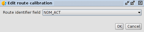
Once selected the attribute containing the routes identifiers and having accepted the dialogue window, another window will appear making the user able to enter the remaining parameters required by this tool.
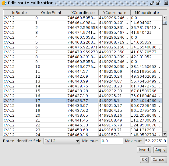
This window contains:
- A table with columns:
- “Route ID”
- “Point” with route vertex order
- “X” with point X coordinate
- “Y” with point Y coordinate
- “M” with point M coordinate
- “ID” indicating the route ID to be changed. It contains all the selected routes identifiers (in case of no selection, it will be filled with all layer ID).
- “Minimum” to indicate the value to be assigned to vertex whose order is 0.
- “Maximum” to indicate the value to be assigned to vertex whose order is the maximum.
- User may shift values in the boxes “Minimum” and “Max” by pressing the “Invert” button.
- By pressing “Apply”, the values of the M coordinate in the table will be recalculated according to “Minimum” and “Maximum” entered values.
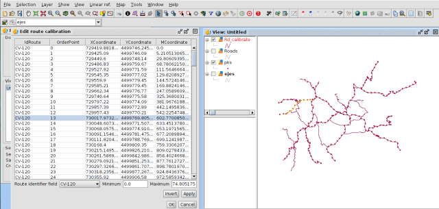
When user selects a “Id”, the table will be populated with the points values of the corresponding “Id” feature. To help user, when selecting an ID, the corresponding route will be highlighted in yellow in the view.
User can manually edit one or more of the M values in the table. As user help, any time you select one or more rows in the table, red dot will be drawn in view in the coordinates corresponding to the vertex being edited.
Instead of hand editing some points, it is possible to make the tool calculate them based on a values range by changing the “Minimum” and “Maximum” table values. Pressing on “Apply”, the M values are recalculated in the table.
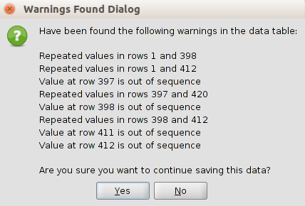
By click on Ok in this window, the tool will check that the M values form an ordered sequence, as well as presence of repeated or negative values. If these value are correct, user may go back before saving changes.
By accepting this dialogue, the M fields values will be permanently assigned to the route points only after having accepted the changes.
Related posts:
- Dynamic segmentation I: https://blog.gvsig.org/2015/11/24/on-the-road-to-gvsig-2-3-dynamic-segmentation-lrs-i/
- Dynamic segmentation (II)/ LRS (I): https://blog.gvsig.org/2015/11/24/on-the-road-to-gvsig-2-3-dynamic-segmentation-lrs-i/
- Dynamic segmentation III. Calibrate Routes: https://blog.gvsig.org/2016/02/22/on-the-road-to-gvsig-2-3-dynamic-segmentation-iii/


Pingback: On the road to gvSIG 2.3: Dynamic segmentation (V) | gvSIG blog
Pingback: On the road to gvSIG 2.3: Dynamic segmentation (VI and final) | gvSIG blog
Pingback: On the road to gvSIG 2.3: Dynamic segmentation (IV) – GeoNe.ws
Pingback: gvSIG 2.3 is now available! | gvSIG blog